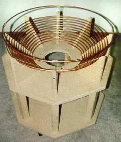
Specifications:
| Material: | 50 feet 1/4" copper tubing |
| Spacing: | 3/8" per turn |
| Inclination: | 45 degrees |
| Turns: | 12-1/4 total |
| Calculated inductance: | 72.7 uH total |
Notes:
Incidentally, this design for the platform and primary support was extremely efficient. I used one 2' x 4' piece of 3/4" particle board. I cut this in half to make (2) - 2' x 2' sections. As it turns out, the length of one side of the octagon is 10", so I did the layout on one board, screwed both of them together, and cut off the corners to make the top and bottom octagons. The 8 cut-off corners now become 45-degree supports for the primary with a hypotenuse of about 10" (which is just right for this tube diameter and spacing). The disk from the secondary hole cut in the center then becomes a bulkhead at the end of the secondary tube to support the torrid discharge terminal. Then I used one 8' - 2" x 2" board and cut into 8 equal lengths for the support legs. The only wood wasted was in the form of saw dust. -- Efficiency I think Tesla himself would be proud of!
I used a router with a 1/4" groove bit to route the grooves. I assembled the coil supports, then uncoiled the primary tube directly from the shipping box into the grooves in the supports. This copper comes soft, however the more you bend and stretch the metal, the harder (and more electrically resistive) it will become (and the more kinks you put in the coil), so it's best to keep the forming process to a minimum. This technique seemed to be remarkably easy, and produced decent results. I was worried about trying to "pre-wind" the coil and finding a suitable form of the right size, but this technique eliminated the hassle.
The
strike rail was fashioned from an additional section of 1/4" tube from
the primary, and supported by 4 -
1"
x 6" strips of 1/8" thick lexan (polycarbonate) plastic. This plastic
is known as "thermo-forming" plastic. If gently heated you can bend
or form it, then let it cool and it will maintain its new shape.
The key is to introduce enough heat to form the plastic without forming
unsightly burns or blisters in the material. I used this forming
technique to form the 1" x 6" strips into a small loop around the strike
rail.
10-31-98 - If you've got a really sharp eye, you'll notice there's only 11-5/8 turns on the primary in the photo. I added about 5/8 turn on the 10-30-98 rebuild by simply soldering the two tube ends together. Let this be a lesson -- It's easier to wind an extra turn or two initially...just 'cause it's there, you don't have to use it!
1-15-99
- I've has several people ask why I went with a 45 degree incline, and
others that swear that it makes the primary "much too close" to the secondary.
My reasons...initially I couldn't decide on a vertical or flat primary,
45 degrees was a perfect compromise. Secondly, once I cut the corners
off of the primary base, I couldn't let those 8 little triangles go to
waste. Finally, if you do the math, the height difference of the
top primary turn between a 45 degree coil and even a 15 degree coil is
only about 3" overall. With millions of volts bussing around up there,
I can't imagine 3" making much difference.
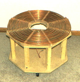
| Material: | 50 feet + 20 feet 1/4" copper tubing |
| Spacing: | 1/4" per turn |
| Inclination: | 0 degrees (flat) |
| Turns: | 17 total |
| Calculated inductance: | 122.5 uH total |
2-6-99 - Well, I guess this teaches me to open my big mouth! I decided to change to an 8" x 24" toroid. This appeared to make a significant difference in the energy levels in the coil. To the extent that I needed to move the secondary up to a height approximately equal to the top turn of the 45 degree primary to lessen the over coupling condition. I decided to rewind my primary in a flat configuration. Additionally, I wanted to add a few more turns to allow room to tune to even lower resonance frequency in the future. I added 20 more feet of 1/4" tubing to the existing 50 feet (70' total). The initial information I gathered when building the coil, about how a flat primary would have UNDERcoupling problems appears to be false, at least in this instance. In the last run on 2-8-99, I still located the bottom turns of the secondary about 3" above the primary to keep interwinding arcs on the secondary to a minimum.
Also you'll probably notice some discoloration of the copper in the "new" picture. Get used to it! I suppose you could try and clear coat the copper, but that would make a good connection with the adjustable primary tap a real pain. And if anybody has some good info and calculations for the "double primary" which has adjustable impedance by moving the two closer/farther apart instead of the adjustable tap, let me know!
And yes, I'm still using some un-sealed wood for the primary support, so I know some energy is going directly to ground right through the wood. Maybe one of these days I will get energetic and spring for some lexan...what then...60 or 70" arcs??
7-26-2000
So
far this primary has remained essentially unchanged. I have added
a strike rail that rests on four wood 1 x 2's. Since the coil tunes
at about 10-12 primary windings, I am going to cut off some of the additional
copper to help prevent "autotransformation" in the unused windings.